|
|
||
|---|---|---|
| .. | ||
| img | ||
| Makefile | ||
| README.md | ||
| modbus_tcp.c | ||
| modbus_tcp.h | ||
| test_modbus_tcp.c | ||
README.md
##modbus-tcp##
1. 简介
在xiuos平台实现modbusTCP协议,包括协议报文组装、解析和数据传输,支持主从通信。
2. 数据结构设计说明
2.1 数据结构定义
首先,需要定义设备存储区的结构体,包括两种存储类型,16位的寄存器和线圈。
//定义存储区结构体
typedef struct MbMemory
{
    coils8_t*rcoil_mem;
    reg_t*rreg_mem;
    coils8_t*rwcoil_mem;
    reg_t*rwreg_mem;
}MBmemoryType;
然后便是关于ModbusTCP协议相关的结构体定义,包括MBAP和PDU,后续数据区视情况而定,长短不固定。
//协议的固定部分为12个字节,当功能码为写多个数据时,后续还有不定长的数据部分
typedef struct mbap
{
    //MbapType
    u16_t tid;
    u16_t pid;
    u16_t len;
    u8_t uid;

    /* data */
}MbapType;

typedef struct pdu
{
    u8_t func;

    u16_t addr;

    u8_t operand1;
    u8_t operand2;
    /* data */
}PduType;
2.1 从设备请求解析和响应部分
主要定义请求的解析器结构,以及每种功能码对应的解析函数,和发送响应的函数。
//定义解析器结构体
typedef struct mbparser
{
    int (*func_set[20])(MBmemoryType*,int,MbapType*,PduType*,u8_t**resp);
}MbParserType;

//功能码解析函数
int FuncReadRwCoilX01(MBmemoryType*mem,int fd,MbapType*mbap,PduType*pdu,u8_t**resp);
int FuncReadRCoilX02(MBmemoryType*mem,int fd,MbapType*mbap,PduType*pdu,u8_t**resp);
int FuncReadRwRegX03(MBmemoryType*mem,int fd,MbapType*mbap,PduType*pdu,u8_t**resp);
int FuncReadRRegX04(MBmemoryType*mem,int fd,MbapType*mbap,PduType*pdu,u8_t**resp);
int FuncWriteRwCoilX05(MBmemoryType*mem,int fd,MbapType*mbap,PduType*pdu,u8_t**resp);
int FuncWriteRwRegX06(MBmemoryType*mem,int fd,MbapType*mbap,PduType*pdu,u8_t**resp);
int FuncWriteRwMcoilsX0f(MBmemoryType*mem,int fd,MbapType*mbap,PduType*pdu,u8_t**resp);
int FuncWriteRwMregsX10(MBmemoryType*mem,int fd,MbapType*mbap,PduType*pdu,u8_t**resp);
int FuncReportSlaveIDX11(MBmemoryType*mem,int fd,MbapType*mbap,PduType*pdu,u8_t**resp);


/**
 * @description: 制作响应报文
 * @param  {MbapType*mbap,PduType*pdu,u8_t**resp,u16_t buf_len}
 * @return {}
 * @Author: pgh_dd 1041315949@qq.com
 * @LastEditors: pgh_dd 1041315949@qq.com
 */
void MakeResponse(MbapType*,PduType*,u8_t**,u16_t);

/**
 * @Description: 发送响应报文
 * @param {int} fd 套接字对应文件描述符
 * @param {u16_t} n 报文大小
 * @return {int}
 * @Date: 2023-07-25 17:24:55
 * @Author: pgh_dd 1041315949@qq.com
 */
int SendResponse(int fd,u8_t**buf,u16_t n);
2.2 主设备的请求包装和发送部分
/**
 * @Description: 读取键盘输入,并生成请求报文
 * @param {u8_t} flag
 * @return {int}
 * @Date: 2023-07-25 17:25:26
 * @Author: pgh_dd 1041315949@qq.com
 * @LastEditors: pgh_dd 1041315949@qq.com
 */
int GenerateModbusRequest(MbapType*,PduType*,u8_t flag,u8_t**request);

/**
 * @Description: 发送请求报文
 * @param {int fd,u8_t**request,int n}
 * @return {}
 * @Date: 2023-07-25 17:26:10
 * @Author: pgh_dd 1041315949@qq.com
 * @LastEditors: pgh_dd 1041315949@qq.com
 */
void SendModbus(int fd,u8_t**request,int n);

/**
 * @Description: 读取请求报文
 * @param {int fd,MbapType*mbap,PduType*pdu}
 * @return {void}
 * @Date: 2023-07-25 17:26:49
 * @Author: pgh_dd 1041315949@qq.com
 * @LastEditors: pgh_dd 1041315949@qq.com
 */
void GetRequest(int fd,MbapType*,PduType*);
3. 测试程序说明
modbusTCP协议基于TCP协议,因此其主从通信实际上是基于TCP的S/C通信,因此分为服务端和客户端。
服务端部分(从设备)程序实际上是一个被动接受请求报文的TCP服务器程序,除了一些基础参数的定义外,主要包括一个无限循环的服务程序,包括报文的接收,以及对存储区的操作,和生成发送响应。
static void *ModbusTcpServer(void *arg)
{
    //设置IP和子网掩码网关
    u8_t uid=1;//定义从设备id和存储区

    MBmemory mbm;//定义存储区
    if(mb_memory_init(&mbm)==-1)//初始化存储区,包括对四个存储区进行内存分配
    {
        return 0;
    };

    MBparser mb_parser;//初始化功能码解析器
    MBparser_init(&mb_parser,MBTCP);//初始化解析器,将功能码对应函数注册

    int fd=create_socket(PORT);//创建监听套接字
    if(fd==-1)return 0;

    if (listen(fd, 10) != 0 ) {
        lw_error("Unable to listen\n");
        close(fd);
        return 0;
    }

    while(1)
    {
        //建立连接,因为每次接受的连接可能不是同一个设备发来的,因此需要把建立连接部分放在循环体内。
        struct sockaddr_in tcp_addr;
        socklen_t addr_len;

        printf("wait accept\n");
        int clientfd = accept(fd, (struct sockaddr *)&tcp_addr, (socklen_t*)&addr_len);

        if(clientfd==-1)
        {
            lw_error("Unable to listen\n");
            return 0;
        }

        while(1)
        {
            MBAP mbap;
            PDU pdu;
            read_mbtcp_MBAP(clientfd,&mbap);//读取数据前7字节为mbap初始化

            if(mbap.uid!=uid){//检验是否为此从机
                close(clientfd);
                break;
            }


            read_mbtcp_PDU(clientfd,&pdu);//读取pdu和一些定长部分

            printf("OP:%x\n",pdu.func);
            printf("ADDR:%x\n",pdu.addr);

            u8_t** response_buf;//定义操作返回的指针
            u8_t buf_len=mb_parser.func_set[pdu.func](&mbm,clientfd,&mbap,&pdu,response_buf);//请求的解析和对存储区的操作

            send_response(clientfd,response_buf,buf_len);//发送响应
            // return NULL;
            //执行操作

        }
        close(clientfd);
    }
    close(fd);
    mb_memory_free(&mbm);//释放存储区
}
客户端部分(主设备)是一个主动发送请求的TCP客户端程序,主要包括一个接受键盘输入的循环体,可以接受用户输入的指令,然后包装成Modbus请求报文,并发送给ModbusTCP服务器,然后接受响应报文。
static void *ModbusTcpClient(void *arg)
{
    u16_t counter=0;
    int fd = -1;
    int ret;

	// lw_print("2023-05-27 Peng Guanhua\n");
    lw_print("%s start\n", __func__);

    fd = socket(AF_INET, SOCK_STREAM, 0);//定义服务器套接字
    if (fd < 0) {
        lw_print("Socket error\n");
        return NULL;
    }

    char tcp_ip_str[128]="192.168.31.148";//服务器ip和端口号
    u16_t tcp_socket_port=6000;

	/*建立套接字连接*/
    printf("%s\n",tcp_ip_str);
    struct sockaddr_in tcp_sock;
    tcp_sock.sin_family = AF_INET;
    tcp_sock.sin_port = htons(tcp_socket_port);
    tcp_sock.sin_addr.s_addr = inet_addr(tcp_ip_str);
    printf("%s\n",tcp_ip_str);

    memset(&(tcp_sock.sin_zero), 0, sizeof(tcp_sock.sin_zero));

    ret = connect(fd, (struct sockaddr *)&tcp_sock, sizeof(struct sockaddr));

    if (ret < 0) {
        lw_print("Unable to connect %s:%d = %d\n", tcp_ip_str, tcp_socket_port, ret);
        close(fd);
        return NULL;
    }

    lw_print("TCP connect %s:%d success, start.\n", tcp_ip_str, tcp_socket_port);


    while (1) {

        MBAP mbap={counter,0,0,0};
        PDU pdu;
        u8_t*request;

        int mesg_len=generate_modbus_request(&mbap,&pdu,MBTCP,&request);//此函数中接收键盘输入,并生成请求报文。
        send_modbus(fd,&request,mesg_len);//发送请求报文。
        get_response(fd,&mbap,&pdu);//接收响应报文,并显示
        counter++;
    }

    close(fd);
    return NULL;
}
4. 运行结果
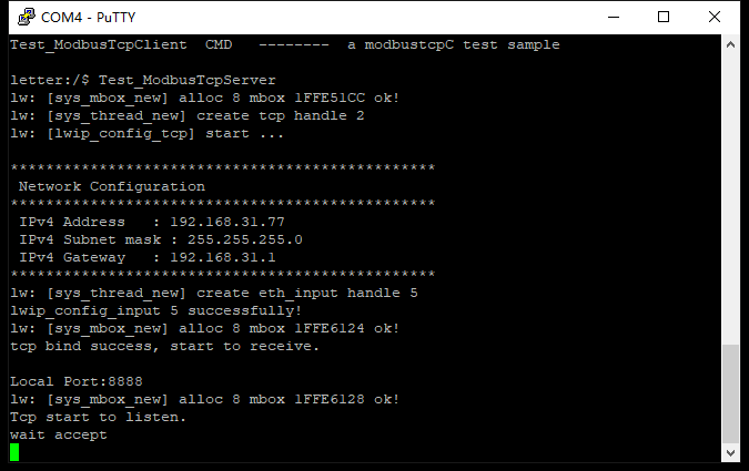
4.1 从设备通信测试
从设备测试,在终端上将TCP服务端程序打开,如图1,等待主设备的连接。
主设备采用Modbus Poll应用程序,建立TCP连接,如图2所示。

此时modbus poll程序便会不断的向从设备发送请求,如图3。

可以看到解析出的功能码、地址以及对应的响应报文,然后我们在modbus poll上修改一下存储区数据。如图4所示。

因为修改的是寄存器存储区的值,因此对应0x10功能码,然后看看从设备的反映。如图5所示。

可见成功收到功能码,并返回了响应的报文。
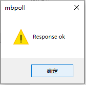
modbus poll显示响应成功,存储区已成功修改期望的值。

可见存储区已成功修改。
线圈部分的查询修改同理,不再赘述。
4.2主设备通信测试
首先打开modbus slave应用程序,用以作为从设备,然后将存储区数据修改,用以测试,并打开TCP端口,等待主设备的连接,如图8所示。

同样在终端打开从设备程序,从设备的ip,port在源码中已定义好,所以打开时已经连接上,如图9所示。

开始输入从设备id,功能码,以及其他信息用以生成请求报文。
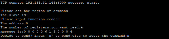
如图10所示,输入功能码3,对应读取寄存器功能,地址从0开始,数量4,然后便会生成请求报文,然后发送,结果如图11所示。

可见,已成功查询到寄存器的值。
然后测试写入功能,输入功能码15(0xf),对应写入多个线圈功能,如图12,modbus slave对应的响应结果如图13所示。

写入线圈的值为5个,分别为1 0 1 0 1。发送成功后,modbus salve中显示如图13所示。
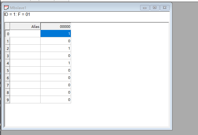
可见,已成功修改。
其他功能码测试过程类似,不再赘述。